Long-term readers know that my mind will eventually turn to tear-downs and electronics. So it goes with digital pianos.
Thanks to the Piano World Forum, I found two links of interest to deep divers.
Inside Yamaha P-515
First up is a long-ish Yamaha P-515 repair video. I’ve got to say, tearing down a P-515 is not for the faint-hearted. We owe Late Night DIY much gratitude for taking the challenge.
I’d loved to include some screensnaps here, but Late Night’s camera work is a little shaky. (Dude shot the video after a late night gig.) Here is a list of things to watch for:
- 5:14: Particle board base.
- 6:57: The AJACK board with external connectors.
- 7:51: The keybed.
- 8:17: Rubber contact strips.
- 9:47: Contact PCB traces.
- 11:10: Key removal.
- 24:11: Speaker box.
- 25:16: AJACK, again. DM board is underneath.
- 27:07: Top of speaker box.
These camera shots should give you a pretty good tour of the insides without going through the whole disassembly and repair narrative.
Disassembly tips: Take pictures while ripping things apart. Mark holes on printed circuit boards. Do not put screws and other hardware in speaker cones!
A few observations. First, look at the size of the particle board base! The wood base provides strength and rigidity for the NWX keybed. The base must weight at least ten pounds. Think about that when hefting your P-515 around.
The AJACK printed circuit board (PCB) has all of the MIDI and audio connectors. The main PCB — the digital logic (DM) mainboard — is underneath the AJACK. I dearly wish we had pictures (top and bottom) of the DM mainboard.
The rubber contact strips beneath the keys have three nubby buttons for each key. The nubby buttons make contact with the PCB contact traces (those squiggly squares). This is the so-called “triple sensor.” Other than three contacts instead of two, the basic hardware tech ain’t different from digital synths. The hardware “sensor” isn’t that sophisticated as all of the smarts are in the scanning software.
The speaker box is cool. I wouldn’t be surprised to see it inside of P-S500, too. Yamaha reuses components to cut costs and spare parts inventory.
The speaker box and NWX key designs are probably patented. I am surprised that the Piano World folks haven’t exploited the U.S. PTO patent database…
Inside Yamaha CLP-685
Several posts on Piano World Forum cite this look into the Yamaha CLP-685.
More than a look, this is one of the most gutsy tear-downs that I’ve seen. Guy buys an expensive CLP-685 and literally takes it apart out of curiosity. I usually play with my toys before taking them apart and I rarely take apart anything over $100 USD retail. That’s some Chinese chutzpah!
This article has a lot of terrific pictures (some a little blurry, unfortunately). There are good close-up pictures of the tan power supply boards and the DMH main digital electronics board.
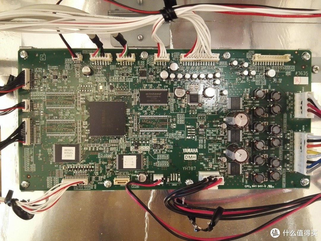
I wish the DMH board legends were legible and I wish that we had a picture of the other side, too. Plain as day is a Yamaha SWX09 (YH621A0) integrated circuit. The SWX09 integrates the main CPU, tone generation and digital effects onto a single chip. I’ll be thinking about this more in days to come, especially the “empty” board real estate. The SWX09 has nearby companions. The Winbond W9864G6KH-6 4M by 16-bit 166MHz SDRAM is DSP working memory for the SWX09. The two labeled ICs are wave ROM. The rest of the components are mounted on the bottom of the board. We see only the components mounted on the top side of the board.
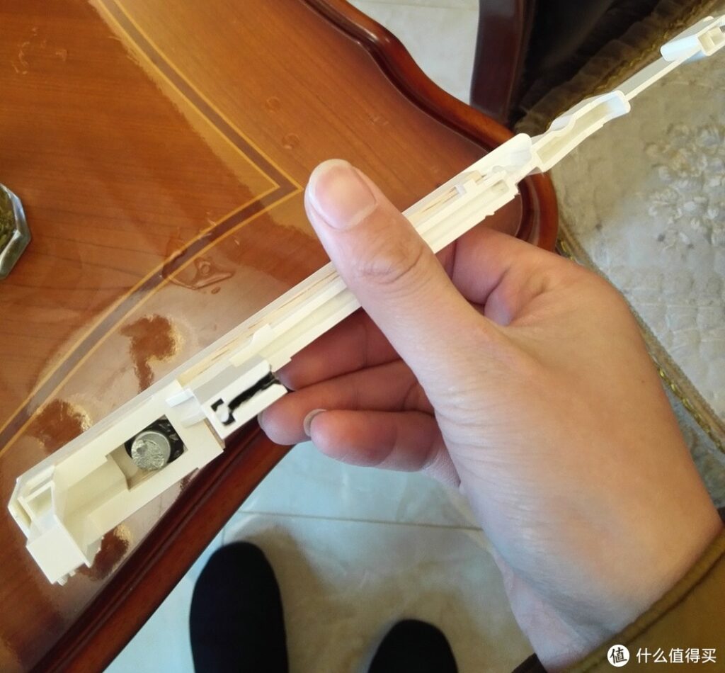
The Piano World Forum folk are positively obsessed with key design and action. Yamaha describe the CLP-685 keybed thus:
GrandTouch keyboard: Wooden keys (white only), synthetic ebony and ivory key tops, escapement
I see a lot of plastic, a metal weight, and a little decorative wood. I’m not hung up on wood vs. plastic as even Einstein would say “Dead mass is dead mass.” If it plays good, why worry? The only concern I have about anything is long-term durability (e.g., those rubber contact strips and dirt).
Hope other musical electronics nerds have found this exposition interesting. 🙂
Copyright © 2023 Paul J. Drongowski