The future looks bright

After reading the owner’s manual and watching the first demonstrations, it’s clear that the Yamaha Genos™ is a beautiful face-lift over the Tyros series, but where is the sonic breakthrough?

As usual, the answer was right in front of my face all along. First, a few facts and figures:

    Feature                        Tyros 5    Genos
    ---------------------------    -------    -----
    Mega Voices                       54        82
    Super Articulation voices        288       390
    Super Articulation 2 voices       44        75
    Live voices                      138       160
    Articulation buttons               2         3

Back before the specifications were officially announced, I saw a leaked version of these specs. Given the big leap in Mega Voice (MV), Super Articulation (SA) and Super Articulation 2 (SA2) voices, I didn’t think the leaked specifications were credible. Now, I believe.

In short, the new tone generation hardware in Genos enables a very large SSD-sized waveform memory capable of holding all of the waveforms needs for the boost in MV, SA and SA2 voices. The end result is greater musical expression, detail and realism for both the Genos player and audiences.

This blog takes a focused look at Mega Voice, Super Articulation (1 and 2), and why the “great leap forward” is possible in Genos. For PSR/Tyros purists, I hope that you don’t mind my shortened abbreviations for Mega Voice, etc. The short abbreviations are much easier to type without extra punctuation marks.

Background information

MV, SA and SA2 are the trinity of highly detailed, expressive Yamaha voices. All three kinds of voices are based on Yamaha’s sample playback technology AWM2 (Advanced Wave Memory). Super Articulation 2 is based on Articulation Element Modeling (AEM). Both AWM2 and AEM are covered by many Yamaha patents.

Yamaha did not introduce these voices in one fell swoop. Mega Voices were the first to appear. A Mega Voice divides a voice into two or more velocity ranges and assigns a different waveform to each range. A trumpet voice, for example, is divided into:

    Velocity range    Waveform
    --------------    ----------------------
         1 - 20       mf trumpet
        21 - 40       f trumpet
        41 - 60       ff trumpet
        61 - 90       Legato
        81 - 100      Straight
       101 - 110      Shake
       111 - 120      Falls
       121 - 127      Glissando up

MIDI notes above C6 and above C8 are mapped to valve noise and breath noise, respectively. For other examples of Mega Voices, see the Mega Voice mapping table in the Tyros 5 Data List file for details. (Also, learn how to create a Mega Voice using Yamaha Expansion Manager.)

The first three ranges and waveforms correspond to velocity switching as we know it. The second five ranges correspond to articulations as we know and love them in software instruments. The articulations and noises are the sonic sweeteners that make sequenced music sound more human and natural.

Mega Voices are intended for sequencing. They are used in arranger keyboard styles to make them sound less MIDI-ish. Unless you have the finger control of a god, you cannot reasonably play a Mega Voice through the keyboard.

But, wait a minute! What if you put some smart software between the keyboard and the tone generator? The smart software watches and analyzes your gestures (i.e., key presses, releases, button pushes, etc.), and plays either a regular note or an articulated note. This is the basic idea behind Super Articulation.

In the case of the trumpet, for example, the SA software watches the notes that you play and if you push the right articulation button while playing a note, the software selects and plays a shake instead of a regular trumpet sound. The SA software also analyzes note timing and plays a legato waveform when you strike a second key while holding the first key. SA software even responds to note intervals such as playing a glissando when the interval between two notes is big enough.

In the end, Super Articulation makes Mega Voice articulations intuitively playable. I thoroughly enjoy playing the SA voices on my PSR-S950. I don’t have too think to hard at all — just let it rip as I hear it in my head.

Montage and late model Motif- and MOX-series synthesizers implement Expanded Articulation (XA). Take a look at my deconstruction of the Tenor To The Max voice.

Super Articulation 2 takes SA up another notch. Real musical tones are not discrete sonic events. Tones tend to blend together due to the characteristics of the musical instrument itself and/or playing technique (e.g., legato). SA2 performs a digital blending between notes by analyzing gestures and selecting the appropriate waveform from a very large database of waveform segments. Broadly speaking, these segments belong to three categories:

  1. Head: Attack portion of the sound
  2. Body: Main body of the sound
  3. Tail: Release portion of the sound

Consider two notes where the first note is detached and the second note is legato. SA2 plays the head segment for the first note, sounding the attack. This is followed by the body of the first note. SA2 does not play a head for the second note. It blends the body of the first note into the body of the second note. When the second note is released, SA2 selects and plays a tail for the second note.

All of this blending is computation heavy and is very sensitive to timing and latency. The technology behind SA2 is Articulation Element Modeling (AEM). AEM is actually a deep subject and is patented. (See my related post about Real Acoustic Sound.)

Technical breakthrough, sonic breakthrough

Folks who are familiar with software instruments and sound libraries know that all of this comes with a cost. Sample libraries for orchestral instruments are enormous because there are so many different ways to bow, pluck, strike and generally mess with acoustic instruments. Tens and even hundreds of gigabytes are needed to store the highest quality sample libraries. Then, one needs to have a fast streaming device like an SSD and a computationally husky CPU to play the samples without a glitch or hiccup.

Before Montage and Genos, Yamaha’s mainstay tone generator (TG) integrated circuit (IC) was the SWP51L. This venerable chip carried the load in Motif, MOX, CP, Clavinova, and other mid- to high-end Yamaha products.

Like all things electronic, the SWP51L’s time eventually came and went. The SWP51L communicates to waveform memory over a CPU-like bus with a fixed width address. The SWP51L is limited in three ways. First, the fixed width address is not big enough to address the very large sample library needed to support today’s articulation-heavy voices. Second, the address bus cannot be (easily) made wider. Third, the bus protocol is not directly compatible with relatively inexpensive commodity NAND flash memory. Conclusion, the SWP51L does not scale to a big waveform memory.

The Montage and the Genos deploy the new generation SWP70 tone generator. Unlike the SWP51L, the SWP70 is compatible with commodity NAND flash memory — the same kind of memory used in solid state drives (SSD). The Open NAND Flash Interface (ONFI) bus protocol — and the Genos — is scalable.

Thus, Yamaha is finally free to expand waveform memory to sample library scale.

People make much of “SSD, SSD, SSD!” SSDs use a SATA bus for communication, a bus that can become a bottleneck in itself. Yamaha have found a way to integrate SSD functionality into the SWP70 without the need for a SATA bus. The integration promises greater speed (i.e., memory bandwidth) without the cost and latency of a SATA bus. This design approach is patented. Please read one of my earlier posts about the SWP70 for the gory technical details. Hope you know a bit about computer architecture before diving in!

I’ve also speculated about the role of the SWP70 in the implementation of the Genos file system. This post is highly speculative and has not been verified by reading the Genos service manual.

What does this mean for the player?

The bottom line for the player and audiences is rich sound filled with detail and realism, thanks to big waveform memory, AWM2/AEM synthesis and Yamaha’s sound development expertise. Big waveform capacity and the new mono/stereo tone generation channels in the SWP70 also mean greater use of stereo samples (“Live voices” in PSR/Tyros-speak.)

Please look at the chart at the beginning of this article. No previous generation-to-generation Tyros upgrade has had such a big jump in the number of Mega Voice, Super Articulation and Super Articulation 2 voices. It can only get better from here as the SWP70 is the Yamaha platform for the next 8 to 10 years.

The Genos promises to be an expressive instrument which will be fun to play. The knobs, sliders and articulation buttons afford a great deal of real time control. I can’t wait to play one of these!

Longer term, what do the technical breakthroughs hold for the Montage series? You ain’t seen or heard nothin’ yet.

Copyright © 2017 Paul J. Drongowski

Genos internal memory: A speculation

Update: 23 December 2017

The article below illustrates the danger of speculation based on a few specifications. It is so easy to convince oneself that “This must be the way they did it!”

Thank goodness for service manuals.

I will eventually write a longer description of the Genos™ compute complex. Here’s a few facts to tide you over:

  • The main CPU is a 1GHz TI AM4376 Sitara Cortex-A9 ARM processor (AM4376BZDN100).
  • There are two SWP70 tone generator (TG) integrated circuits.
  • The master TG has 2GBytes (physical) of wave memory (Winbond W29N08GVSIAA).
  • The slave TG has 4GBytes (physical) of wave memory.
  • The internal memory is a Toshiba 64GByte eMMC device (THGBMGG9T4LBAIR).

The eMMC device is where you’ll find the “58GByte internal memory.” The eMMC is connected to one of the ARM’s two MMC interfaces.

The Montage’s main CPU is an 800MHz TI AM3352 Sitara Cortex-A8 ARM processor (AM3352BZCZ80). Whose the big brother and the little tag-along? 🙂

Everything about the following speculation (below) is utterly wrong. That’s why I try to explicitly label speculation and fact when writing.

A (Discredited) speculation

First, you have to get the mule’s attention.

Yamaha Genos™ hasn’t hit the streets yet and here is a speculative article about its hardware design…

I’d like to thank Kari V., Mihai and Joe H. on the PSR Tutorial Forum for getting this mule’s attention. They deserve the credit.

Spex

Here are a few Genos specifications that drew curious looks:

  • Polyphony: 256 (max.) (128 for Preset Voice + 128 for Expansion Voice)
  • Voice expansion memory: Approximately 1.8GBytes
  • Internal memory: Approximately 58GBytes

Normally, a Tyros has a large hard disk inside for bulk storage. The hard drive contains a file system to hold style files, song files, text files and a whole lot more. The Tyros 5 shipped with a 500GB hard disk drive. Tyros 5 internal memory — some form of non-volatile flash — is spec’ed at approximately 6.7MBytes. Yes, megabytes.

Word from the demonstrations is that the Genos has neither a hard disk drive nor a solid state drive (SSD). Thus, “Internal memory” is not directly user expandable or upgradeable. Eliminating the hard disk drive, the bracket and access door makes good sense because it reduces weight and chassis complexity. SSDs are still a little pricey for a cost-sensitive manufacturer like Yamaha. If it’s not a hard drive and if it’s not an SSD, then what is it?

Next, what’s up with that polyphony spec? 128 voice polyphony when you play preset voices only and 128 voice polyphony when you play a voice from user voice expansion memory? That’s rather unorthodox.

The high-level view

This is where the Yamaha SWP70 tone generator (TG) integrated circuit (IC) comes into the story.

The SWP70 uses ONFI-compatible NAND flash as its waveform memory. “ONFI” is the industry standard Open NAND Flash Interface. ONFI-compatible chips are the same NAND flash used in SSDs. The SWP70 caches the waveform data in a fast SDRAM just like an SSD in order to have fast, random access to samples.

Yamaha have created a tone generator IC that integrates an SSD-like flash and cache controller. This design eliminates the cost and latency of the SATA bus which normally connects an SSD within a PC or Mac.

For the hardware inclined, here’s a short speculative answer. There are two tone generator ICs each having their own ONFI flash memory. One TG and flash memory (call this one “TG A”) handles factory presets. The other TG and flash memory (call this “TG B”) handles user expansion voices.

The “TG B” flash memory is 64GBytes of ONFI NAND flash. Through software, it is partitioned into a file system partition (62GB?) and a user expansion voice partition (2GB).

The file system partition contains the initial factory content (4GB). The remaining space (58GB) is the “Internal memory” quoted in the Genos specifications.

So, Yamaha engineering decided to use space in one of the ONFI flash memories for bulk storage in order to cut the weight and expense of a magnetic hard drive (heavy) or an SSD (lighter than a hard drive, but not cheap).

If this is true — if — then there are some positive implications for the future of Genos. More at another time.

Ingenious, yes. User expandable, no.

Do I know this for sure? Oh, hell no. We need a service manual. Even a visual inspection of the digital logic board (DM) might not be conclusive.

The low-level view

The notional diagram below shows some of the major interfaces to the SWP70. [Click on images to enlarge.]

  • The CPU bus connects the SWP70 to the main control CPU and other major subsystems that require CPU-based data and control.
  • The ABUS allows SWP70s to communicate with each other when more than one SWP70 is in a system.
  • The waveform memory (NAND flash) communicates with the SWP70 over a Open NAND Flash Interface (ONFI) bus. This open industry standard lets Yamaha use commodity flash memory for waveform ROM. Waveform memory is split into upper and lower bytes with shared control signals. This arrangement instantly doubles bus bandwidth versus a single ONFI data channel.
  • The Serial audio bus brings audio data into the SWP70 (e.g., from the ADC) and sends audio data to the DACs and other subsystems.

Then, the fun begins. The SWP70 has three parallel SDRAM memory channels for wave and DSP working memory.

  • The DSP working memory is a large, scratch-pad memory for effect computation. I believe this memory is also the working memory for Montage FM-X.
  • The Wave working memory is a fast, read/write data cache which holds samples after they are read from the waveform memory. Remember, NAND flash favors sequential block mode read access, transferring data on the nibble-serial ONFI bus. The wave working memory plays the same role as the data cache in an SSD storage unit.

Memory capacities vary across products depending upon target polyphony, effect workload and, of course, the sample set.

Here are capacities for the PSR-S770, PSR-S970 and Montage. All capacities are physical (i.e., raw physical storage space).

             AWM     Waveform    Wave     DSP
          Polyphony   Memory   Working  Working
          ---------  --------  -------  -------
PSR-S770     128      512MB      32MB     8MB
PSR-S970     128       2GB       32MB     8MB
Montage      128*      4GB       32MB    16MB
          * Stereo/mono

The Montage DSP working memory is twice as large as the PSR-S970 reflecting the larger number of supported effect units.

The ONFI standard is the same standard used in solid state drives (SSD). Thus, Yamaha can reap the benefit of lower cost commodity flash. The wave working memory caches data just like an SSD. The SWP70 design yields maximum bandwidth to and from NAND flash without the expense or latency of a SATA bus. Thanks to ONFI, Yamaha can increase waveform memory size by dropping in higher capacity ONFI-compatible devices. User waveform (voice) expansion memory resides in these same memory components, so one should expect bigger user expansion memory in the future as well as bigger factory sample sets.

The SWP70 reads and writes two flash memories in tandem effectively sending a 16-bit word on each ONFI bus cycle. (See diagram below.) One memory provides the HIGH byte and the other memory provides the LOW byte. The same ONFI control signals are sent to both. For people who like to trash Yamaha for not using SSD, please note that tandem access doubles the transfer bandwidth over a single ONFI data path solution. (Of course, an SSD could do the same thing.)

I’ll bet that using the ONFI waveform memory for file system access made the tone generation guys nervous. Would file system traffic rob memory bandwidth from the tone generators?

Yamaha know latency. They spend a lot of time, money and intellectual effort understanding latency and conquering it. That’s where the second waveform working memory comes into play. Samples heading to the tone generators could be held in one waveform working memory while file system data could be held in the second, separate working memory. This organization separates the memory traffic and prevents file access from disturbing the critical, must-be-predictible sample stream. When the two channels arbitrate for the ONFI bus, the sample stream feeding tone generation could be given priority.

Copyright © 2017 Paul J. Drongowski

Inside Reface YC and CP

Like the Yamaha Reface DX and CS, the Reface YC and CP are brother and sister.

The Reface DX and CS use the Yamaha proprietary SSP2 integrated circuit (IC) for sound synthesis. A few minor hardware differences and the front panel aside, the main difference between DX and CS is software. The YC and CP designs are analogous although the tone generation method and hardware are different.

Sample playback and memory bandwidth

Many people focus on the computational aspects of tone generation and wave memory size, not realizing that memory bandwidth is just as important, if not critical, for sample playback. Waveform samples need to flow from wave memory to the tone generation apparatus whether tone generation is performed on a CPU or a proprietary tone generator IC like Yamaha’s previous generation SWP51L and the now current SWP70.

Sustainable polyphony depends on memory bandwidth. If available bandwidth is low, then polyphony is low. Raise bandwidth and you can raise polyphony, too, provided adequate computational resources (e.g., tone generation channels or CPU cycles) are available.

Several factors affect memory bandwidth.

  • The most obvious factor is the raw speed of the memory technology. Fast memory means high bandwidth.
  • Next is the kind of memory communication channel: shared or dedicated. If waveform samples and CPU code reside in the same physical memory component, then bandwidth must be shared between the CPU and the tone generator, lowering tone generation bandwidth and polyphony. Bandwidth is higher when the CPU and tone generator each have their own memory channel and component. Concurrency wins!
  • Bandwidth sometimes depends on the read access mode or pattern of the memory component. Concerns here include random vs. sequential access, word vs. paged, etc. This subject is a little too deep for this short note.
  • Finally, bandwidth depends on the bus organization: serial or parallel. Parallel buses move each bit in a word on a dedicated wire. Serial buses move moves sequentially on one or a few wires. Parallel is fast; serial is slower.

Of course, there are further factors and choices like the necessity for read-write access, non-volatile data storage, and so forth.

The instrument designer faces the challenge of supplying sufficient memory bandwidth, tone generation channels and polyphony at a particular price point. Polyphony and price point are market-driven requirements. Memory bandwidth and tone generation resources are technological. The designer must work within both kinds of requirements and constraints.

Internet discussions tend to dwell on memory speed and component cost alone, neglecting system-level design costs like board complexity, wiring and testing. A simple rule of thumb is, “More IC pins and wires means higher system cost.” Serial communication decreases pins and wires, but it compromises bandwidth. Shared buses also decrease the number of pins and wires, again, penalizing bandwidth. One expects to find serial communication and/or shared buses in low price products, while higher price products can reap the benefits of dedicated, parallel communication.

I must note that commodity bulk flash memory uses a serialized memory bus, but it does so by sequential paged reads and data caching. The SWP70 is compatible with commodity flash and uses a dedicated RAM cache to achieve high sample bandwidth. This scheme is cheaper than the SWP51L with its parallel dedicated wave bus.

Processor primer

Yamaha have several different processors at their disposal for main CPU, tone generation and effect processing (DSP) chores:

  • SWLxx: SWL processors, like the SWL01U, have integrated CPU, tone generation and DSP resources in the same IC. CPU instructions, data and waveform samples travel on the same shared bus. SWL processors are typically designed into value (i.e., entry-level) products. SWLs are also low power and ready for battery operation.
  • SWXxx: SWX processors have integrated CPU, tone generation and DSP resources on the same IC. CPU, tone generation and DSP each have a dedicated memory channel. SWX processors often appear in mid-range products.
  • SWPxx: SWP processors have a large number of tone generation and DSP elements, and no main CPU. The SWPs must be controlled by a separate main CPU.
  • SSP2: The SSP2 has an integrated CPU and DSP elements. The SSP2 is not used in AWM2 applications, appearing instead in computationally intensive synthesis engines (Reface CS and DX), vocal harmony processors, and digital mixers.

The SWL, SWX and SSP2 series processors are true “system on a chip (SOC)” designs with analog-to-digital conversion, bit-serial data (UART), USB, SPI and other interfaces. The CPU core is usually a variant of the Renesas SH architecture family. Architectural commonality facilitates code reuse across products. Yamaha have damned good engineers.

There are two different types of SWX processor: SWX02/SWX03 and the SWX08. The 02/03 variants appear in lower priced mid-range products. Examples include the MOX6 (SWX02), PSR-S650 (SWX02) and Piaggero NP-32 (SWX03). The SWX08 appear in the upper mid-range: PSR-S770, Reface YC and Reface CP.

Sometimes an SWX processor is used as the main computer controlling an SWP. For example, the SWX02 is the main computer in the MOX6/MOX8, controlling an SWP51L. Similarly, the SWX08 is the main computer in the PSR-S750, controlling an SWP51L. In both cases, the SWP51L handles all tone generation duties. Yamaha increases fabrication volume when it uses an SWX in this way.

At this point, semiconductor folks might ask if Yamaha fuses off TG or DSP deficient SWX08s and assigns them to main computer duty only. This strategy cuts waste as it deploys SWX08s with perfectly good CPUs and faulty, fused off TG and/or DSP circuitry. This is standard practice throughout the industry, so please don’t freak out.

Reface YC and Reface CP

The Yamaha Reface YC and the CP share the same digital logic board design. The main large-scale integrated (LSI) components are:

IC CPU (SWX08)   Yamaha R8A02042BG         SH-2A CPU core
Work SDRAM       Winbond W9812G6JH-6       8M x 16-bit word, 166MHz
DSP SDRAM        Winbond W9864G6KH-6       4M x 16-bit word, 166MHz
Program/Wave YC  Cypress S29GL256S90TFI020 16M x 16-bit word NOR flash
DAC              Asaki Kasei AK4396VF-E2   192kHz, 24-bit stereo DAC
Panel scan CPU   MB9AF141LAPMC1            ARM Cortex-M3 (32-bit core)
ADC              TI PCM1803ADBR            96kHz, 24-bit stereo ADC

The same ARM Cortex-M3 (32-bit core) processor is used in the Reface CS and Reface DX for panel and keyboard scan. Potentiometers and so forth are sensed by the ARM’s 12-bit analog to digital converter (ADC). Key scanning is performed through GPIO lines. (I don’t see any way to expand beyond 37 keys, unfortunately.)

The SWX08 is the main control computer. It handles the 5-pin MIDI interface and the USB interface. The ARM communicates with the SWX08 over a serial link (UART). Integral tone generation and DSP elements synthesize digital audio and effects.

The AK4396VF-E2 digital to analog converter (DAC) is also used in the PSR-S770 and PSR-S970 arranger workstations (among other Yamaha products.) The Montage employs the AK4393VM-E2 DAC by way of comparison. Digital audio for the internal speakers is converted by the Yamaha YDA176 digital amplifier.

The PCM1803ADBR ADC sends serial digital audio (24-bit I2S format) to the SWX08 where it is mixed with the synthesized tones.

DSP processors on the SWX08 have their own dedicated 16-bit data channel to DSP SDRAM (i.e., working memory for effects). The wave memory (NOR flash ROM) has a dedicated 16-bit parallel channel for samples. Wave memory is labelled “E:64MB / O:32MB”. Presumably, this means that the CP needs 64MBytes for electric piano waveforms and the YC needs 32MBytes for organ waveforms. I wonder if Yamaha substitute a larger, pin-compatible flash ROM in the Reface CP? I don’t have the Reface CP service manual in order to resolve this conjecture.

Summary

So, there you have it. Yamaha wisely designed the CS and DX as a pair and designed the CP and YC as a pair. I’m sure that shared board designs reduced their manufacturing costs.

Reface sales seem to be coming to an end. Nearly all Reface models have sold through in North America. Yamaha has either decided to cancel the Reface after the first production run or they will launch Reface 2.0, perhaps with full-size keyboards. They could easily design the guts of the YC and/or CP into the Piaggero NP-12 chassis. That would make for one killer, battery-powered stage machine!

Copyright © 2017 Paul J. Drongowski

Tip-toe through the tech

Last year ’bout this time, we were all holding our collective breath awaiting the new Yamaha Montage. There are two products which I expect to see from Yamaha sometime in the next one to two years:

  1. The successor to the mid-range MOXF synthesizer, and
  2. The successor to the top-of-the-line (TOTL) Tyros arranger workstation.

NAMM 2017 seems a little too soon for both products. In the case of the MOXF successor, Yamaha conducted marketing interviews during the summer of 2015. I would guess that MOXF sales are still pretty good and no new products from the usual suspects (Korg, Roland) are visible on the horizon. The Krome and FA could both use an update themselves. Not much market pressure here at the moment. (Korg’s NAMM 2017 announcements are, so far, a little underwhelming.)

Read my MOX retrospective and interview follow-up.

I suspect that the Tyros successor is somewhat closer to launch. Speculation has been heated ever since Yamaha filed for a US trademark on the word mark “GENOS”. The word mark was published for opposition on November 15, 2016. “Published for opposition” means that anyone who believes that they will be damaged by registration of the mark must file for opposition within 30 days of publication. If “GENOS” is indeed the name for the Tyros successor, then the 30 day period ending December 15, 2016 is cutting it very close to NAMM 2017. Even more ludicruous if Yamaha were to begin manufacturing products printed with that name for a NAMM 2017 launch. Imagine the scrap if opposition was successful!

For quite some time, I have been meaning to summarize the key U.S. patents that I believe to be GENOS-related. (Assuming that “GENOS” is the name!) I’ve procrastinated because the launch date is most likely fall 2017 at the earliest as previous Yamaha mid- and high-end arranger models are typically launched in the fall in anticipation of the holiday selling season.

A much larger barrier is the task of reading and gisting the patents. Patents are written in legalese and are much more difficult to read than the worst written scientific papers! One of the folks on the PSR Tutorial forum suggested making a list of the top five technologies for the new TOTL arranger. I generally hate the superficial nature of “list-icles,” but the suggestion is a good one. Nothing will get done as long as the barrier is big because I would much rather jam and play! I’m supposed to be retired.

The 2016 Yamaha annual report states that Yamaha want to make innovative products which are not easily copied by competitors. Patents — legally protected intellectual property — are essential to achieving this goal. Generally, a company only applies for a patent on technology in which they have a serious business interest due to the significant cost of obtaining and maintaining patent protection.

So, here are a few of Yamaha patented technologies which could appear in future products — perhaps GENOS, perhaps others.

SWP70 tone generator

This may seems like old news…

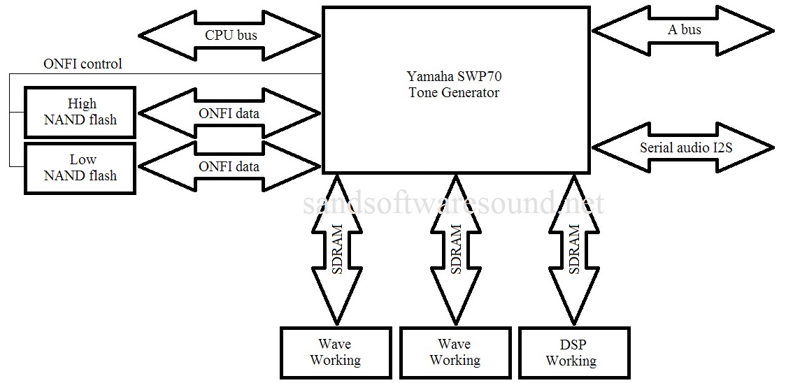
The next generation SWP70 tone generator first appeared in the mid-range Yamaha PSR-S970 arranger workstation. The SWP70 made its second appearance in the Yamaha Montage synthesizer. The S970 incorporates only one SWP70 and does not make full use of the chip. (At least three major interfaces are left unconnected.) In keeping with Yamaha’s TOTL design practice, the Montage employs two SWP70 integrated circuits: one each for AWM2 sample-playback and FM. A second sample cache interface on the AWM2 side is unconnected.

The Tyros successor likely will use two SWP70 tone generators, too. The number of available tone generation channels with two SWP70s will be massive (512 channels). Yamaha could opt for a single SWP70 and still outmatch the current generation Tyros 5. Like the Montage, there will be enough insert effect DSP processors to cover each style and user part, as many as two for every part.

It will be interesting to see (and hear) if the GENOS will make use of the second sample cache interface. A second cache would not only support more tone generation channels, but might be necessary for long, multi-measure musical phrases that are needed for full audio styles (discussed below).

The SWP70 flash memory interface follows the Open NAND FLASH interface (ONFI) standard, the same as solid state drives (SSD). ONFI memory devices can be stacked on a bi-directional tri-state bus, so potentially, the GENOS could support a large amount of internal waveform storage. This flash memory will contain the “expansion memory,” that is, physical memory reserved in flash memory for user waveforms. The expansion flash memory expansion modules (FL512M, FL1024M) are dead, Jim.

If you’re interested in Yamaha AWM2 tone generation, here’s a few patents to get you started:

  • Patent 9,040,800 Musical tone signal generating apparatus, May 26, 2015
  • Patent 8,383,924 Musical tone signal generating apparatus, February 26, 2013
  • Patent 8,389,844 Tone generation apparatus, March 5, 2013
  • Patent 8,957,295 Sound generation apparatus, February 17, 2015
  • Patent 8,035,021 Tone generation apparatus, October 2011
  • Patent 7,692,087 Compressed data structure and apparatus and method related thereto, April 6, 2010

U.S. Patent 8,957,295 is the patent issued for the SWP70 memory interface. U.S. Patent 9,040,800 describes a tone generator with 256 channels — very likely the SWP70.

Pure Analog Circuit

This may seem like old news, too, since Pure Analog Circuit (PAC) debuted in the Yamaha Montage.

Pure Analog Circuit is probably the least understood and least appreciated feature of the Montage. It’s not just better DACs, people. The high speed digital world is very noisy as far as analog audio is concerned. Yamaha separated the analog and digital worlds by putting the DACs and analog electronics on their own printed circuit board away from noisy digital circuits. Yamaha then applied old school engineering to the post-DAC analog circuitry, paying careful attention to old school concerns like board layout for noise minimization and clean power with separate voltage regulation for analog audio. Yamaha’s mid- to high-end products have always been quiet — PAC is pristine.

Since the PAC board is a separate, reusable entity, I could see Yamaha adopting the same board for GENOS.

Styles combining audio and MIDI

Yamaha are constantly in search of greater sonic realism. Existing technologies like Megavoices and Super Articulation 2 (Advanced Element Modeling) reproduce certain musical articulations. However, nothing can really match the real thing, that is, a live instrument played by an experienced professional musician. PG Music Band-in-a-Box (BIAB), for example, uses audio tracks recorded by studio musicians to produce realistic sounding backing tracks. The Digitech TRIO pedal draws on the PG Music technology for its tracks. (“Hello” to the Vancouver BC music technology syndicate.)

Yamaha have applied for and been granted several patents on generating accompaniment using synchronized audio and MIDI tracks. Here is a short list of U.S. patents:

  • Patent 9,147,388 Automatic performance technique using audio waveform data, September 29, 2015
  • Patent 9,040,802 Accompaniment data generating apparatus, May 26, 2015
  • Patent 8,791,350 Accompaniment data generating apparatus, July 29, 2014
  • Application 13/982,476 Accompaniment data generating apparatus, March 12, 2012

There are additional patents and applications. Each patent covers a different aspect of the same basic approach, making different claims (not unusal in patent-land). Yamaha have clearly invested in this area and are staking a claim.

The patents cite four main motivations, quoting:

  1. The ability to produce “actual musical instrument performance, human voices, natural sounds”
  2. To play “automatic accompaniment in which musical tones of an ethnic musical instrument or a musical instrument using a peculiar scale”
  3. To exhibit the “realism of human live performance”
  4. To advance beyond known techniques that “provide automatic performance only of accompaniment phrases of monophony”

Your average guy or gal might say, “Give me something that sounds as natural as Band-in-a-Box.” Yamaha sell into all major world markets, so the ability to play ethnic instruments with proper articulation is an important capability. Human voice, to this point, is limited to looped and one-shot syllables, e.g., jazz scat. The new approach would allow long phrases with natural intonation. [Click on images in this article for higher resolution.]

audio_accompaniment_tracks

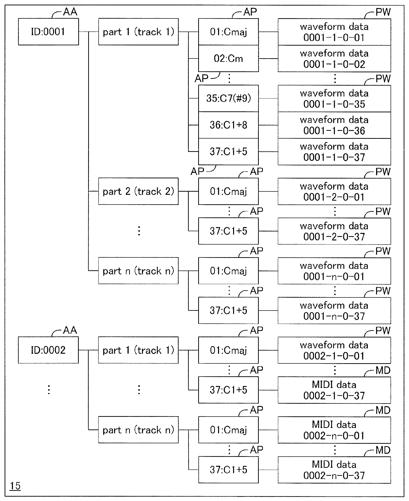
Currently, mid- and high-end Yamaha arrangers have “audio styles” where only the rhythm track is audio. The patents cover accompaniment using melodic instruments in addition to rhythm instruments. The melodic audio tracks follow chord and tempo changes just like the current MIDI-based styles. Much of the technical complexity is due to synchronization between audio and MIDI events. Synchronization is troublesome when the audio tracks contain a live performance with rubato. Without good synchronization, the resulting accompaniment doesn’t feel right and sounds sloppy.

Accompaniment from chord chart

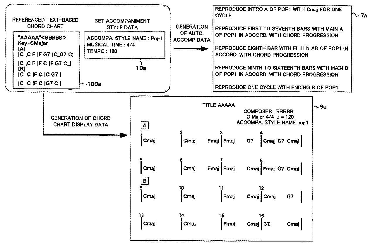
This next feature will be very handy. U.S. Patent 9,142,203 is titled “Music data generation based on text-format chord chart,” September 22, 2015. If you use textual chord charts (lyrics plus embedded chord symbols), you will want this!

chord_chart_example

Simply put, the technique described in this patent translates a textual chord chord to an accompaniment. The accompaniment is played back by the arranger. The user can select tempo, style, sections (MAIN, FILL IN) and so forth.

The translator/generator could be embedded in an arranger or it could be implemented by a PC- or tablet-based application. Stay tuned!

Selectively delayed registration changes

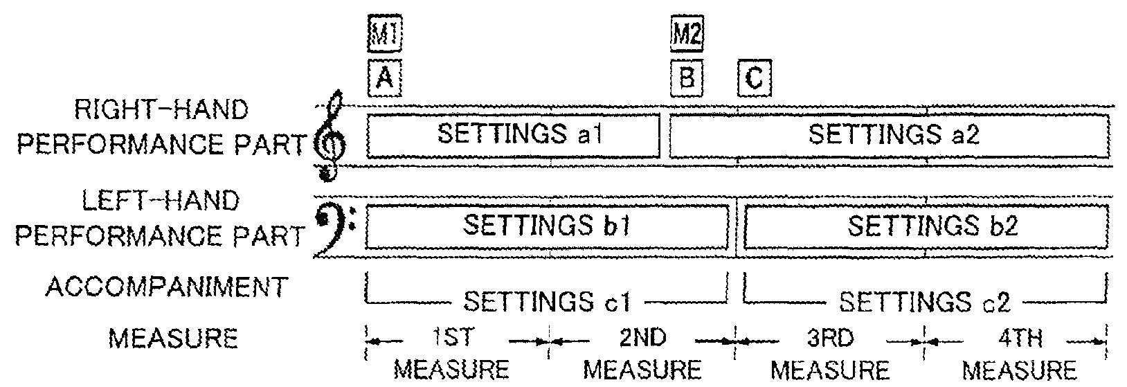
A registration is a group of performance parameters such as the right hand voice settings, left hand voice settings, accompaniment settings, and so forth. Mid- and high-end arrangers have eight front panel buttons where each button establishes a set of parameter values (“readout”) when the button is pushed. It’s the player’s job to hit the appropriate button at the appropriate time during a live performance to make voice settings, etc. A player may need a large number of buttons, if a musical performance is complicated.

Usually only a few parameters are different from one registration to the next. Recognizing this, the technique described by U.S. Patent 9,111,514 (“Delayed registration data readout in electronic music apparatus,” August 18, 2015) delays one or more parameter changes when a button is pushed. The user specifies the parameters to be delayed and the delay (such as the passage of some number of beats or measures, etc.) Thus, a single registration can cover the work of multiple individual registrations.

delayed_registration

I’ll have to wait to see the final product to assess the usefulness of this feature. Personally, I’d be happy with a configuration bit to keep OTS buttons from automatically turning on the accompaniment (ACCOMP). Sure would make it easier to use the OTS buttons for voice changes.

Ensembles / divisi

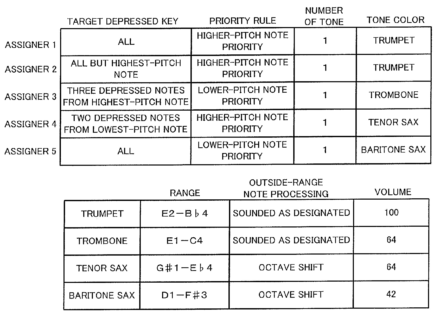
Tyros 5 ensemble voices assign played notes to individual instrument voices in real time, allowing a musician to perform divisi (divided) parts. Tyros 5 ensembles can be tweaked using its “Ensemble Voice Key Assign Type List.” Types include open, closed, and incremental voice assignment. U.S. Patent 9,384,717, titled “Tone generation assigning apparatus and method” and published July 5, 2016, extends Tyros 5 ensemble voice assignment.

The technique described in 9,384,717 gives the musician more control over part assignment through rules: target depressed key, priority rule, number of tones to generated, note range, etc. The rules handle common cases like splitting a single note to two or more voices.

ensemble_rules

These extensions could lead to some serious fun! I didn’t feel like the Tyros 5 ensemble feature was sufficiently smart and placed too many demands on the average player, i.e., less-than-talented me. The rules offer the opportunity to shift the mental finger work to software and perhaps could lead to more intuitive ensemble play. Neat.

Voice synthesis

As I alluded to earlier, arrangers make relatively primitive use of the human voice. Waveforms are usually limited to sustained (looped) or short (one-shot) syllables.

Yamaha have invested a substantial amount of money into the VOCALOID technology. VOCALOID draws on a singer database of syllable waveforms and performs some very heavy computation to “stitch” the individual waveforms together. The stitching is like a higher quality, non-real time version of Articulated Element Modeling (AEM).

VOCALOID was developed through a joint research project (led by Kenmochi Hideki) between Yamaha and the Music Technology Group (MTG) of the Universitat Pompeu Fabra in Barcelona, Spain. VOCALOID grew from early work by J. Bonada and X. Serra. (See “Synthesis of the Singing Voice by Performance Sampling and Spectral Models.”) More recent research has stretched synthesis from the human voice to musical instruments. Yamaha hold many, many patents on the VOCALOID technology.

Patent 9,355,634, titled “Voice synthesis device, voice synthesis method,” is a recent patent concerning voice synthesis (May 31, 2016). It, too, draws from a database of prerecorded syllables. The human interface is based on the notion of a “retake,” such as a producer might ask a singer to make in a recording studio using directives like “put more emphasis on the first syllable.” The retake concept eliminates a lot of the “wonky-ness” of the VOCALOID human interface. (If you’ve tried VOCALOID, you know what I mean!) The synthesis system sings lyrics based on directions from you — the producer.

An interface like this would make voice synthesis easier to use, possibly by novices or non-technically oriented musicians. The big question in my mind is whether voice synthesis and editing can be sped up and made real time. Still, wouldn’t it be cool if you could teach your arranger workstation to sing?

Music minus one

This work was conducted jointly with the MTG at the Universitat Pompeu Fabra. A few of the investigators were also involved in VOCALOID. Quoting, “The goal of the project was to develop practical methods to produce minus-one mixes of commercially available western popular music signals. Minus-one mixes are versions of music signals where all instruments except the targeted one are present.”

This is not good old center cancellation. The goal is to remove any individual instrument from a mix regardless of placement in the stereo field. You can hear a demo at http://d-kitamura.sakura.ne.jp/en/demo_deformation_en.htm.

I doubt if this technique will appear on an arranger; the computational requirements are too high and the method is not real time. However, “music minus-one” is very appealing to your average player (that is, me). My practice regimen includes playing with backing tracks. I would love to be able to play with any commercial tune on whim.

There are patents:

  • US Patent 9,002,035 Graphical audio signal control
  • US Patent 9,224,406 Technique for estimating particular audio component
  • US Patent 9,070,370 Technique for suppressing particular audio component

and there are scientific papers:

  • “Audio Source Separation for Music in Low-latency and High-latency Scenarios”, Ricard Marxer Pinon, Doctoral dissertation, Universitat Pompeu Fabra, Barcelona, 2013.
  • D. Kitamura, et al., “Music signal separation by supervised nonnegative
    matrix factorization with basis deformation,” Proc. DSP 2013, T3P(C)-1, 2013.
  • D. Kitamura, et al., “Robust Music Signal Separation Based on Supervised Nonnegative Matrix Factorization with Prevention of Basis Sharing”, ISSPIT, December 2013.

Music analysis

Yamaha have put considerable resources into what I would call “music analysis.” These technologies may not (probably will not) make it into an arranger keyboard. They are better suited for PC- or tablet-based applications.

I think we have seen the fruits of some of this labor in the Yamaha Chord Tracker iPad/iPhone application. Chord Tracker identifies tempo, beats, musical sections and chords within an audio song from your music library. It displays the extracted info in a simple chord chart and can even send the extracted “lead sheet” to your arranger. The arranger plays back the “lead sheet” as an accompaniment using the selected style.

We’re probably both wondering if Chord Tracker will integrate with the chord chart tool described above. Stay tuned.

Yamaha Patent 9,378,719 (June 28, 2016) is a “Technique for analyzing rhythm structure of music audio data.” Patent 9,117,432 (August 25, 2015) is an “Apparatus and method for detecting chords.” I wouldn’t be surprised if Chord Tracker draws from these two patents.

Yamaha has also investigated similarity measures and synchronized score display:

  • Patent 9,053,696 Searching for a tone data set based on a degree of similarity to a rhythm pattern, June 9, 2015
  • Patent 9,006,551 Musical performance-related information output device, April 14, 2015
  • Patent 9,275,616 Associating musical score image data and logical musical score data, March 1, 2016

I’m not sure where Yamaha is going with similarity measures and searching. Will they use similarity measures to selected accompaniment phrases? Who knows?

The work on score display synchronizes the display of the appropriate part of a musical score with its live or recorded performance. These techniques may be more appropriate to musical education and training, particularly for traditional brass, string and woodwind players. Yamaha derives considerable revenue from traditional instruments and this is perhaps a way to enhance their “ecosystem” for traditional acoustic instruments.

Score display is one possible application of Yamaha’s patented technique to transmit performance data via near-ultrasonic sound. The technique borrows one or more tone generation channels to generate the near-ultrasonic data signal. See my earlier post about U.S. Patent 8,779,267 for more details.

So long for now!

That’s it! I hope you enjoyed this brief tour through a few of Yamaha’s recent patent grants and filings.

If you want more information about a particular patent, then cruise on over the the U.S. Patent and Trademark Office (USPTO) web site. Navigate to patent search and plug in the patent number.

Copyright © 2017 Paul J. Drongowski

Montage: The hardware platform

The Yamaha Montage is one heck of a fine keyboard! Let’s take a quick look inside.

The Montage hardware is a new platform. Sure, there are a few things borrowed from older products, but that’s like blaming Apple for reusing a USB controller. The digital and analog electronics are all new.

There are several printed circuit boards and I will only cover the main PCBs.

  • PNL/PNR: Handles the front panel buttons, knobs, sliders, master volume and gain.
  • LCD: Bridge between the LCD controller in the main CPU and the 7inch TFT WVGA LCD touch panel.
  • DJK: Digital jacks (foot controllers, foot switch, sustain, MIDI)
  • AJK: Analog electronics and jacks (DACs, ADC, balanced/unbalanced outputs, analog input, phones).
  • DM: Digital electronics (main CPU, tone generators, external USB and Ethernet interfaces).

A few ports and connections are “Debug only” and are not populated or used in normal operation. The Ethernet port to the main CPU is debug only, for example.

The separation of the digital and analog electronics and jacks is significant. When the Montage was first introduced, I mentioned that “Pure Analog Circuit (PAC)” appeared to be an exercise in old school engineering that pays careful attention to board layout, component selection and clean power. The AJK board bears this out. The AJK board contains the stereo DAC and ADC components:

  • Audio ADC: Asahi Kasei AK5381VT-E2 24-bit ADC (96KHz max)
  • Audio DAC assignable output: Asahi Kasei AK4393VM-E2 24-bit DAC (96KHz max)
  • Audio DAC main output and phones: Asahi Kasei AK4393VM-E2 24-bit DAC

The ADC and DACs communicate with the DM board over an audio backbone. Physical separation keeps digital circuits (with fast rise/fall times) away from analog signal paths. The AJK board also has its own voltage regulators. They ain’t kiddin’ about PAC!

Yamaha adopted ARM architecture processors for the first time in the Reface series. (See my article about the Reface CS and Reface DX internals). Montage continues this trend.

  • The PNL board contains an MB9AF141NA ARM microcontroller with a 40MHz internal clock. The ARM microcontroller is assisted by a Toshiba TMP89FW24AFG microcontroller (SOC) operating at 10MHz. In Yamaha’s terminology, this ARM is a “sub CPU.”
  • The main CPU is an AM3352BZCZ80 ARM microprocessor with an 800MHz CPU clock. It is a Texas Instruments Sitara ARM Cortex-A8 single core MPU.

The ARM Cortex-A8 is a major departure from the Motif line which employed MIPS architecture microprocessors (such as the Toshiba TX4939C) as the main CPU.

We first saw the new SWP70 tone generator in the Yamaha PSR-S970 arranger workstation. The SWP70 replaces the SWP51L which has been the mainstay in mid- to upper-tier Yamaha products for several years. Top-tier products (e.g., Motif XF and Tyros 5) have two SWP51L tone generator chips which together share a common wave memory. The two SWP51Ls split AWM2 voice and DSP duties.

So, it isn’t any surprise to see two SWP70s in the Montage. What is suprising, however, is how the Montage’s two SWP70s are deployed. The two SWP70s are not connected in the “classic” structure. Instead, the microarchitecture is assymetric.

  • TG Master: The TG Master is connected to wave ROM (flash), wave RAM (SDRAM), and DSP RAM (SDRAM).
  • TG Slave: The TG Slave is connected to DSP RAM (SDRAM) and an SSP2 processor (through an ASIC gate array bridge).

I’ll have more to say about the SSP2 in a moment. The bridge connects the TG Slave’s serial audio interface to the SSP2 and the bridge carries several channels of digital audio (I2S format) to/from the TG Slave and the SSP2.

Of course, one’s first thought is to presume that the TG Master handles AWM2 voices and the TG Slave handles FM-X voices. There’s a lot of generation and DSP resources within an SWP70, so I doubt if they are left idle in the TG Slave even though the TG Slave does not have memory memory! There is a sixteen bit wide bus between the TG Master and Slave — not really sufficient to carry the sample bandwidth needed for AWM2 tone generation, however.

Each SWP70 has 16MBytes of SDRAM for DSP working memory. The TG Master has 32MB of Wave RAM. The Wave RAM is a cache for samples that are read from wave flash. (See my earlier article about the SWP70 and U.S. Patent 9,040,800.) Commodity NAND flash (as one would find in an SSD) favors sequential access; random access is horribly slow. The Wave RAM caches samples that are read from NAND flash.

Now, the big question: How much wave memory? The Montage wave memory consists of four Spansion (Cypress) S34ML08G101TFI000 8Gbit, ONFI-compliant devices with a total physical capacity of 4GBytes. In classic fashion, the memory is separated into upper and lower bytes. The Yamaha specifications state wave size as, “Preset: 5.67 GB (when converted to 16 bit linear format), User: 1.75 GB.” Assuming a 2.52 aggregate compression factor, the arithmetic works out in the following way:

    4GB physical = (5.67GB / 2.52) preset + 1.75GB user

The Motif series has an aggregate compression factor in this ballpark.

The Montage has a common multi-channel serial audio bus (I2S format) that interconnects the main CPU, TG Master, TG Slave, SSP2, ADC and audio DACs. This is the digital audio backbone. The bus conveys digital audio from the generators and effects on the DM board to (from) the converters on the AJK board.

The SSP2 is a Yamaha proprietary processor which is used in many products: Reface CS, Reface DX, PSR-S950 workstation, etc. The SSP2 integrates signal processing, USB, serial audio, and more. It is the “designated hitter” for Yamaha designs. When Yamaha needs a flexible chip with DSP and interfacing skills, it calls on the SSP2. (Roland have a similar jack of all trades called the “ESC2.”)

The Montage’s SSP2 has only 2MBytes of NOR flash memory on its CPU bus. That’s not a lot of program space! The SSP2’s USB port is connected to the external “USB TO HOST” interface. The SSP’s other interfaces convey digital audio to/from the digital audio backbone and the TG Slave. Thus, the SSP2’s main role is to route digital audio. The Montage can send 16 channels and receive 3 channels of stereo 24 bit/44.1 kHz digital audio to/from an external computer or iOS device

Commentary and opinion

I hope you find this quick overview to be informative and helpful. I try to present the system structure objectively without too much speculation.

Please discuss the Montage responsibly! Yamaha have a definite design style which exploits their expertise in very large scale integration (VLSI) as a strategic advantage. When Yamaha specify maximum polyphony as “128 AWM2 and 128 FM-X”, that’s 128 each all day long without any dependencies on the number of effects in use, etc. Some people lament this approach and wish that Yamaha would base their systems on x86 even though x86 is not always the best choice for embedded systems. Yamaha are no strangers to x86 having obtained many patents covering x86-based tone generation back in the 1990s and early 2000s.

Before anyone carries on about SSDs and SATA, please study the design of the SWP70. The SWP70 memory interface has all of the power, flexibility and Open NAND Flash Interface (ONFI) compatibility as an SSD without the need for SATA bus protocol.

Users may rightfully be disappointed at the lack of user-installable expansion memory. Yamaha are not evil; they simply do not have a convenient way to provide user-installable memory at the chip level. I think users should lobby for more built-in expansion memory, but they shouldn’t delve into conspiracy theories about Yamaha’s engineering or managerial practice.

Some wag will undoubtably complain about “memory parts cost only $10,” “my jump drive is 32GBytes,” “the need to stream 100s of gigabytes,” etc. Fine. But, an instrument design is a just one design. It is what it is is. One should listen to the Montage with their ears, then question whether gobs of samples would improve the playability, sound or expression of the Montage. Also, if you really believe that you can build a better instrument at the same price point, by all means, line up the VCs and engineers, go to work, and compete.

The final result is what we hear with our ears. The hardware is important, but it is simply a platform for the “soft content” — the algorithms, code, waveforms and sound design. In the long run, the soft content is the biggest development expense and is the most important element in a successful digital musical instrument product.

Perspective. Chill. Peace.

Here are links to related articles on this site:

All site content is Copyright © Paul J. Drongowski

Reface YC and DX teardowns

Markus Fuller posted two Yamaha Reface teardowns (YC and DX) to Youtube:

In case you’re not familiar with the term “teardown,” think of a teardown as a casual tour through the insides of a keyboard.

Both Reface keyboards have an ARM FM3 handing the user interface panel. The switch to ARM is major news. In the past, Yamaha used Renesas H8 or SH4 microcontrollers for interface applications. They apparently have decided to ride the embedded cost curve and that curve leads to ARM, the current leader in low-power, high function embedded microcontrollers.

I wonder if Yamaha will adopt ARM in their entry-level keyboards? This would be a smart move. Yamaha currently use their own SWL01 processor in battery-powered entry-level products. Now that Yamaha have sold off their integrated circuit fabrication plant, they are free to move to off-the-shelf parts when it makes sense. ARM is the choice for battery-powered embedded devices. Further, the ARM-resident, XG-capable sound engine in Yamaha Mobile Music Sequencer has a better spec than the entry-level ‘boards. (MMS reference)

Both Reface keyboards have a large metal plate over one or more integrated circuits. This is the honey pot. 🙂 I understand Markus’s reluctance to remove the heat sink. This is, however, where the digital signal processing (DSP) is being performed. Apparently, Yamaha had a minor power dissipation problem and resolved it using a simple heat sink (no fan). Heat is an important product design problem; x86 fans take note. (More on x86 and instrument design.)

Here are some notes about the integrated circuits in the Reface YC:

Winbond W9864G6KH-6 SDRAM  (64Mbits)
    4Mx16 bits = 1M words x 4 banks x 16 bits (8MBytes equivalent)
    166MHz/CL3
    Parallel interface
    Burst-oriented accesses

Winbond W9812G6JH-6 SDRAM (128Mbits)
    8Mx16 bits = 2M words x 4 banks x 16 bits (16MBytes equivalent)
    Parallel interface
    166MHz/CL3
    Burst-oriented accesses

AKM AK4396VF (Asahi Kasei Microdevices Corporation)
    Digital-to-analog converter (DAC)
    24-bit 192KHz 128x oversampling
    I2S data interface
    Integrated digital filter

Texas Instruments / Burr Brown PCM1803A
    Stereo analog-to-digital converter
    24-bit, 64x or 128x oversampling
    I2S data interface

The circuits are all pretty typical for a Yamaha design. Not enough information here to indicate whether the SWP70 tone generator is in use or not. Yamaha have used W9864G6KH as DSP SDRAM in past designs.

I’m glad that Markus posts his teardowns. I like it when he zooms in and identifies the integrated circuits. One very small quibble with the YC teardown — I believe the “A” stands for “Acetone.”

While you’re here, catch my Reface CP snap review.

The SWP70 tone generator

As I mentioned in an earlier post, the Yamaha PSR-S770 and PSR-S970 arranger workstations have a new tone generator (TG) integrated circuit (IC) — the SWP70. (“SWP” stands for “Standard Wave Processor.”) The SWP70 is a new TG family in a long line of Yamaha tone generators. The SWP70 replaces the SWP51L, which has been the mainstay in recent generations of Tyros, upper range PSR, Motif, and MOX series workstations.

The SWP70 has much in common with the SWP51L, but also some very significant differences. The SWP70’s external clock crystal frequency is 22.5792 MHz versus 11.2896 MHz for the SWP51L. This funky looking clock rate is a multiple of 44,100 Hz:

    22.5792MHz = 44,100Hz * 512

Samples are transferred to the DAC, etc. at a multiple of 44,100 Hz (Fs). Thus, it makes sense to derive Fs and its multiples from the chip-level master clock. The higher crystal frequency and faster memory read clocks lead me to believe that the SWP70 is clocked twice as fast as the SWP51L.

I am comparing SWP characteristics as deployed in the S970 (SWP70) and the S950 (SWP51L) workstations. This keeps the basis of comparison even although many characteristics (clock rates, DSP RAM size) are the same in higher end models like Tyros 5 or Motif. Higher end models employ two SWPs in master/slave relationship and both SWPs share the same wave memory. For more information about the PSR-S970 internal design, look here.

Five interfaces are essentially the same as the SWP51L:

  1. CPU interface: Communicate with the Main CPU (e.g., Renesas SH7731) via the parallel CPU bus.
  2. Serial audio: Send/receive audio data to/from the DAC, audio ADCs, and main CPU.
  3. Clock interface: Synchronize serial audio data transfers (generate multiples of Fs).
  4. DSP SDRAM interface: Store working data for effect processing.
  5. EBUS interface: Receive controller data messages (e.g., pedal input, keyboard input, pitch bend, modulation, live knobs, etc.) from front panel processors.

The DSP SDRAM is the same size: 4Mx16bits (8MBytes). The SWP70 read clock is 95.9616 MHz, while the SWP51L read clock is 45.1584 MHz. This is more evidence for a higher internal clock frequency.

The Tyros 4, Tyros 5 and S950 have an auxiliary DSP processor for vocal harmony. The microphone analog-to-digital (ADC) converter is routed directly to the auxiliary processor. Prior to these models, the microphone ADC is connected to the tone generator. With the SWP70, the S970’s microphone ADC is once again routed to the SWP70 and the auxiliary processor disappears from the design. Thus, vocal harmony processing (fully or partially) is located in the SWP70. See my post about SSP1 and SSP2 for further details.

The biggest change is the wave memory interface.

A little history is in order. The SWP51L (and its ancestors) were designed in the era of mask programmable ROM. I contend that tone generation is memory bandwidth limited and the earlier interface design is driven by the need for speed. The SWP51L (due to its evolved history) has two independent wave memory channels (HIGH and LOW). Each channel has a parallel address bus (32 bits) and a parallel data bus (16 bits). The two channels account for over 100 pins. (System cost is proportional to pin count.) The user-installed, 512/1024MB flash DIMMs plug directly onto the two channels.

The SWP70 wave memory interface takes advantage of new NAND flash memory technology. The interface is described in US patent application 2014/0123835 and is covered by Japanese patent 2012-244002. I analyzed the US patent application in an earlier post.

The SWP70 retains the HIGH port and LOW port structure. Each port communicates with an 8Gbit Spansion S34ML08G101TFI000 NAND flash device. Address and data are both communicated over an 8-bit serialized bus. This technique substantially decreases pin count and the resulting board-/system-level costs. Smart work.

I did not anticipate, however, the introduction of a new parallel memory interface called “wave-work”. The wave work interface communicates with a 16Mx16bit (32MBytes) Winbond W9825G6JH-6 SDRAM. The read clock is 95.9616 MHz.

The purpose of the wave work SDRAM is revealed by US Patent 9,040,800. This patent discloses a compression algorithm that is compatible with serialized access to the wave memory. The wave work SDRAM is a cache for compressed samples. The characteristics of the Spansion memory device give us a clue as to why a cache is required:

    Block erase time               3.5ms    Horrible (relative to SDRAM)
    Write time                     200us    Terrible
    Random access read time         30us    Bad
    Sequential access read time     25ns    Very good

As the patent explains, two (or more) samples are required to perform the interpolation while pitch-shifting. If there is only one tone generation channel, access is paged sequential. However, random access is required when there are multiple tone generation channels. (The patent mentions 256 channels.) Each channel may be playing a different voice or a different multi-sample within the same voice. One simply cannot sustain high polyphony through random access alone. The cache speeds up access to recently used pages of uncompressed samples.

The wave work interface takes additional pins, thus adding to board- and system-level costs. The overall pin count is still lower when compared to SWP51L. The penalty must be paid in order to use contemporary NAND flash devices with a serialized bus. This is the price for catching the current (and future) memory technology curve.

A few SWP70-related printed circuit board (PCB) positions are unpopulated (i.e., IC not installed) in the PSR-S970. There is an unpopulated position for a second Winbond W9825G6JH-6 wave work SDRAM which would expand the wave work memory to 32Mx16bit (64MBytes). A larger cache would be needed to support additional tone generation channels. Perhaps only half of the tone generation channels are enabled in the mid-grade PSR-S970 workstation.

There is what appears to a second separate wave work interface that is completely unpopulated. The intended memory device is a Winbond W9825G6JH-6, which is consistent with the existing wave work interface.

The PSR-S970 also has a stubbed out interface that is similar to the DSP SDRAM interface. The existing DSP SDRAM signals are labeled “H” for HIGH while the unused interface is labeled “L” for LOW. Perhaps only half of the hardware DSP processors are enabled for the mid-grade S970, waiting to be activated in future high-end Tyros and Motif products.

I refer to future high end products by the names of the current product lines. Yamaha may choose to rebrand future products (e.g., the much-rumored “Montage” trademark).

The Spansion S34ML08G2 8-Gb NAND device is Open NAND Flash Interface (ONFI) 1.0 compliant. The S34ML08G2 device is a dual-die stack of two S34ML04G2 die. The 8-bit I/O bus is tri-state allowing expansion e.g., multiple memory devices sharing the same I/O bus and control signals with at most device enabled at any time. The SWP70 has additional chip select pins that would support this kind of expansion. The current expansion flash DIMMs will no longer be needed or used.

In this note, I concentrated on observations and fact, not speculation about future products. I’ll leave that fun for another day!

All site content is Copyright © Paul J. Drongowski unless indicated otherwise.

SSP1 and SSP2: Designated hitter

One notable absence from the Yamaha PSR-S970 design is the “SSP2” integrated circuit (IC) which handles vocal harmony processing. The SSP1 and SSP2 appeared in the Tyros series and PSR series coincident with Vocal Harmony 2.

For you signal sleuths, the PSR-S950 and Tyros 5 microphone input is routed to an analog-to-digital converter (ADC) where the analog signal is sampled and digitized. The digital sample stream is sent to the SSP2 IC. The firmware munges on the samples and voila, the SSP2 produces a vocal harmony signal that is mixed with samples from the tone generator, etc. The SSP2 sends its results to the TG where effects and mixing are performed. The TG sends its output to the digital-to-analog converters (DAC) and digital amplifiers. The Tyros 4 has the same signal flow using an earlier model “SSP1” processor instead.

Previous machines with vocal harmony (e.g., Tyros 3 and earlier, PSR-S910 and earlier), routed the digitized microphone stream to a tone generator (TG) IC such as the SWP51L. Presumably, vocal harmony processing was performed in the TG IC. With the brand new SWP70 tone generator in the S970, the digitized microphone stream is sent to the SWP70. Looks like vocal harmony processing is folded into the SWP70 TG.

I didn’t give the SSP2 much thought or investigation, and just assumed that it was a gate array or something. On inspection, the pin-out resembles a Renesas embedded DSP processor with analog inputs and outputs, digital I/O, USB and all of the usual suspects. The SSP2 in the S950 has 2MBytes of NOR flash program ROM (organized 1Mx16bits) and 2MBytes of SDRAM (organized 1Mx16bits). The clock crystal is a leisurely 12.2884MHz although the SDRAM read clock is 84.7872MHz.

Mysteriously, a web search on the part numbers doesn’t turn up much information. The part numbers are:

    Schematic ID  Manufacturer?       Yamaha
    ------------  ------------------  --------
    SSP1          MB87S1280YHE        X6363A00
    SSP2          UPD800500F1-011-KN  YC706A0

The PSR-S950 parts list does not give a Yamaha order number for the SSP2. If the SSP2 fails, you’ll need to call Yamaha 24×7 directly.

A web search does turn up a few of the interesting places where the SSP has been seen. In addition to Tyros 4, Tyros 5 and S950, the SSP and SSP2 are featured in:

    PSR-S500 arranger (probable role: effects processor)
    EMX5016CF mixer (role: SPX effects and user interface)
    Steinberg UR22 audio interface
    Steinberg MR816 Firewire audio interface
    Yamaha THR modeling guitar amplifier

The SSP is Yamaha’s designated hitter when they need an odd bit of DSP work done.

PSR-S770 and S970 internal architecture

Yamaha just recently introduced the new PSR-S770 and PSR-S970 arranger workstations. As usual, I’m always anxious to dive into the service manual and see what’s up.

First, I’d like to thank Uli and capriz68 on the PSR Tutorial Forum for their help. Uli made a very nice table from my ramblings, so be sure to check it out there.

Without further introduction, here is a table comparing previous generation models (PSR-S750 and PSR-S950) against the new models.

                    PSR-S750  PSR-S950   PSR-S770  PSR-S970
                    --------  ---------  --------  ---------
Main CPU            SWX08     SH7731     SH7731    SH7731
Clock rate (MHz)    135.4752  256        320       320
Tone generator      SWP51L    SWP51L     SWP70     SWP70
Ext clock (MHz)     11.2896   11.2896    22.5792   22.5792
DSP SDRAM (MBytes)  8         8          8         8
DSP RCLK (MHz)      45.1584   45.1584    95.9616   95.9616
Mic ADC                       AK5381     PCM1803   AK5357
AUX IN ADC          AK5357    AK5381     AK5357    AK5381
DAC                 AK4396    AK4396     AK4396    AK4396
Digital amp         YDA164C   2*YDA164C  YDA164C   2*YDA164C
Wave ROM (MBytes)   256       256        512       2048
Wave SDRAM          N/A       N/A        32MBytes  32MBytes
SSP2 chip           No        Yes        No        No

The main CPU remains a Renasas SH4AL-DSP CPU. The clock speed is increased from 256MHz to the 320MHz, which is just shy of the rated maximum for the SH7731.

Wave memory is increased from 256MBytes (S950) to 512MBytes (S770) and 2GBytes (S970). Part of the S770 and S970 wave memory is reserved for expansion pack voices: 160 MBytes (S770) and 512 MBytes (S950). How Yamaha uses the rest of the memory is up to Yamaha. However, we are now in an era when we cannot compare products solely on the basis of physical wave memory size. Our ears and performance experience are more important than mere byte counts!

The S970 has two NAND flash memory devices labelled “audio style.” The devices are:

    4Gbit NAND flash = 512MBytes
    2GBit NAND flash = 256MBytes
                       ---------
    Total audio style  768MBytes

Yamaha specifies memory size in bits, so one must be careful to convert during analysis. The PSR-S950 has a NAND flash device labelled “Program ROM,” which presumably served the same purpose as well as holding the operating system image that is loaded at boot time. The S950 device capacity is 512MBytes (4Gbits). The S970 reserves 128MBytes for audio style expansion.

The upper mid-range model, i.e., the S970, is biamplified with two digital power amps. The older S950 is also biamplified. Not much change here.

The big news is that Yamaha have a new tone generator integrated circuit (IC), the SWP70. The SWP70 uses the serialized wave memory interface that I described in an earlier post. The SWP70 appears to operate at twice the speed of the older SWP51L. The SWP70 has implications for other future products, so I will analyze it in a separate post.

With respect to the PSR-S970, however, there is another evolutionary step. With the appearance of the new SWP70, there is also the disappearance of the SSP2 IC. The introduction of the SSP2 IC coincided with the introduction of Vocal Harmony 2 in both the Tyros line and the PSR-S950. It is reasonable to infer, then, that vocal harmony is implemented on board SSP2. With the PSR-S970, there are two possibilites.

  1. Vocal harmony is assigned to the now faster main CPU, or
  2. SSP2 functionality is integrated into the new SWP70.

The SWP70 is beefed up in other ways including a new wave working memory.

The future looks interesting as always!

Here are links to my articles on other members of the PSR and Tyros product families:
What’s inside of a Yamaha arranger?
A follow-up on the Yamaha SWP51
Yamaha arranger product family

All site content is Copyright © Paul J. Drongowski unless otherwise noted.